Ford Tps Wiring Color Code
Us Shift Technical Support
Part 1 Throttle Position Sensor Tps Test Ford 5 0l 5 8l

Ford Tps Wiring Color Code Roti Repeat2 Klictravel Nl
Throttle Position Sensor Wiring Diagram 1997 1998 Ford 4 6l 5 4l

Pin On Auto Electrical
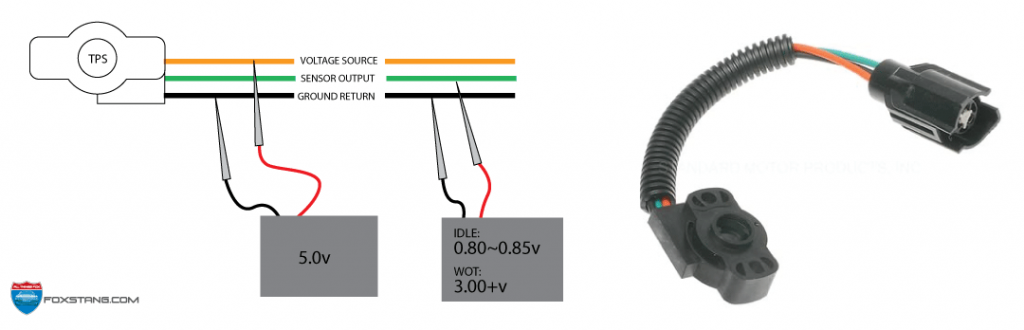
The Complete Fox Mustang Efi Sensors And Things Foxstang Com

1988 ford aerostar minivan wiring information.
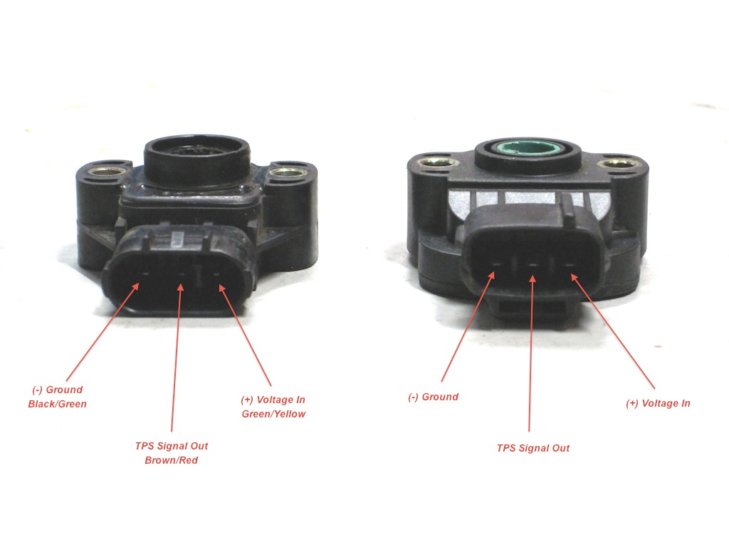
Ford tps wiring color code. Variety of ford f150 wiring diagram. Throttle position sensor tps wiring terminations gnd rtn signal 5v terminal location in connector a b c bs3 harness wire color black white red red gnd rtn signal 5v terminal location in connector b c a bs3 harness wire color black white red red gnd rtn signal 5v terminal location in connector a b c ford wire color black green orange. F150 f250 f350 crown victoria e150 e250 e350. Van ford econoline 1986 van wiring information.
1993 ford f150 2dr pickup wiring information. 1991 ford aerostar minivan wiring information. Ford throttle position sensor connections ford has two different color codes for throttle position sensors and several different connectors and pin outs. Van ford econoline 1993 van wiring information.
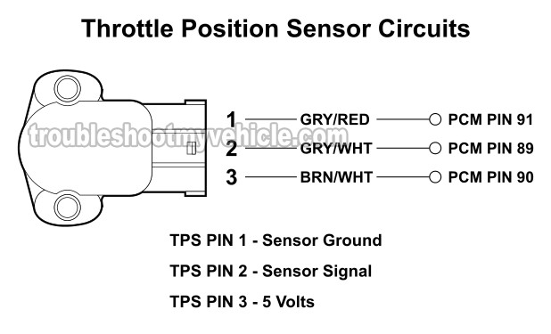
It shows the components of the circuit as simplified forms and also the power and also signal links between the tools. This unique kit was designed by ford. Brn wht wires feeds the tps 5 volts dc. Ford ranger wiring by color 1983 1991.
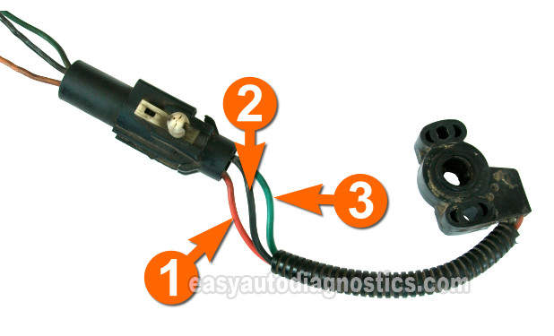
This procedure is a mute point if you have the wiring diagram but often times you just need to actuate the electronic throttle to do a cleaning and run the electronic throttle t p s though the. Black with orange stripe wire power from starter relay to red with orange stripe wire yellow with light green stripe wire yellow wire yellow with white stripe wire alternator and fuse block. 1988 ford ranger 2dr pickup wiring information. 186 ford ltd 4dr sedan wiring information.
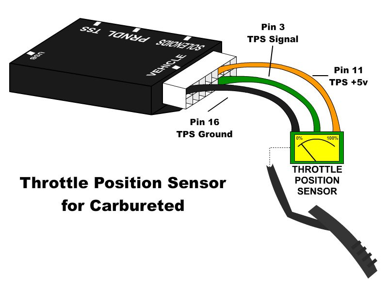
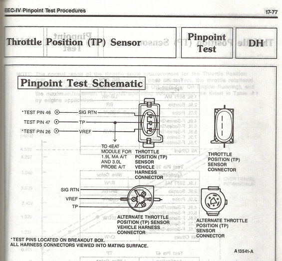
In support of this new wire repair procedure ford is pleased to release to the field the new integrated wire splice tool kit. Black is ground and should be tapped into the black main ground wire from vehicle pin 16 orange is the 5 volt reference feed to the. A wiring diagram is a streamlined conventional pictorial depiction of an electric circuit. The gry red wire feeds ground.
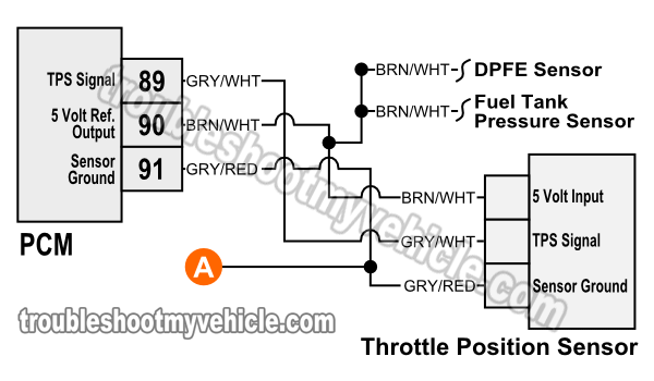
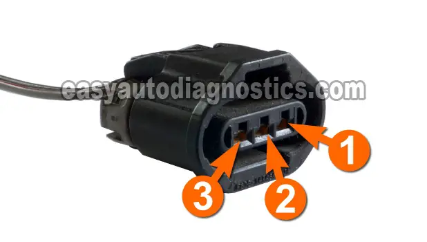
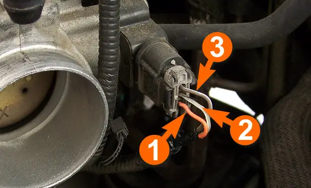
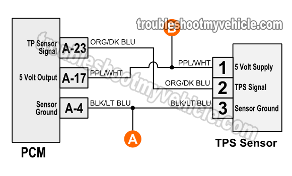
The pcm has a 60 pin connector and on the back side of the connector wire side are embossed a few numbers to further aid you in correctly identifying the pins circuits. The gry wht wire carries the tp signal to the pcm. The illustration above and pin out table below apply only to. Throttle position sensor tps wiring diagram 1997 1998 ford 4 6l 5 4l.
P1120 ford meaning the throttle position sensor responds to the accelerator pedal movement the tps is a rotary potentiometer sensor that provides a signal to the powertrain control module that is linearly proportional to the throttle plate shaft position as the tps is rotated by the throttle shaft the following operating conditions are determined by the pcm.

Ro 5954 Throttle Position Sensor Wiring Diagram Wiring Diagram
Part 1 How To Test The 4 6l 5 4l Ford Throttle Position Sensor Tps

Db 5617 Tps Wire Diagram Furthermore Honda Tps Sensor Diagram

Part 1 How To Test Throttle Position Sensor Ford 1 9l 2 0l

Ce 0809 Dodge Throttle Position Sensor Wiring Diagram Free Diagram
Part 1 How To Test The 3 0l Ford Throttle Position Sensor Tps
Wrg 3749 Tps Wiring Diagram
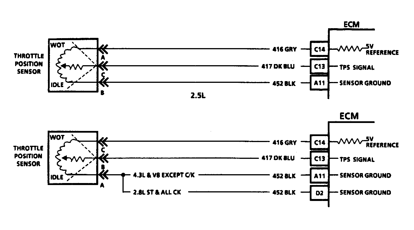
1996 1998 Throttle Position Sensor Circuit Diagram Dodge 3 9l
Part 3 How To Test The Tps 1996 1999 3 8l Windstar

Distribution Box Ford Ranger Wiring Color Codes Wiring Diagram

Electronic Throttle Motor Wires Identification Youtube
Timing And Tps Questions Bronco Zone